Tech Search

Custom Search

Thursday, July 30, 2009

Long fight with Computer Viruses

Long fight with Computer Viruses
I have been a long fight with viruses in my computer system. So, i could not continue my blogging on technical topics. All of sudden my system was functioning so slow. I could not find how to rectify from this problem. I was using a trial version anti virus software installed in my system. I was also struggling with other trial version anti virus software. It could able to detect the viruses, however it could not remove the viruses.
Finally i decided to buy licensed version of anti virus software. I bought a new Internet Security 2009 anti virus software. Before that i formatted my computer system C drive. Then After installing the OS, i installed my new antivirus software. After updating the antivirus software, i had a complete computer scan. It is so terrible to see the result of scanning, my files has had thousands of viruses. Now my system is completely free from viruses.
Finally, i inferred that only a licensed antivirus could remove all viruses from the system, so we can safely run our computer system

Tuesday, July 21, 2009

PCB Design basics

PCB Design basics
Electronics circuits are designed using Printed Circuit Boards. Sometimes we do not know the procedures to do a PCB design. PCBs form the core of electronic equipment domestic and industrial. Some of the areas where PCBs are intensively used are computers, process control, telecommunications and instrumentation. I would like to share the various steps in PCB design here.

1. MANUFACTURING
The manufacturing process consists of two methods; print and etch, and print, plate and etch. The single sided PCBs are usually made using the print and etch method. The double sided plate through – hole (PTH) boards are made by the print plate and etch method.
The production of multi layer boards uses both the methods. The inner layers are printed and etch while the outer layers are produced by print, plate and etch after pressing the inner layers. The software used in our project to obtain the schematic layout is MICROSIM.
2. PANELISATION
Here the schematic transformed in to the working positive/negative films. The circuit is repeated conveniently to accommodate economically as many circuits as possible in a panel, which can be operated in every sequence of subsequent steps in the PCB process. This is called penalization. For the PTH boards, the next operation is drilling.
3. DRILLING AND PLATING
PCB drilling is a state of the art operation. Very small holes are drilled with high speed CNC drilling machines, giving a wall finish with less or no smear or epoxy, required for void free through hole plating. The heart of the PCB manufacturing process. The holes drilled in the board are treated both mechanically and chemically before depositing the copper by the electro less copper platting process.

4. ETCHING
Once a multiplayer board is drilled and electro less copper deposited, the image available in the form of a film is transferred on to the out side by photo printing using a dry film printing process. The boards are then electrolytic plated on to the circuit pattern with copper and tin. The tin-plated deposit serves an etch resist when copper in the unwanted area is removed by the conveyor’s spray etching machines with chemical etch ants. The etching machines are attached to automatic dosing equipment, which analyses and controls etch ants concentrations.

5. SOLDERMASK
Since a PCB design may call for very close spacing between conductors, a solder mask has to be applied on the both sides of the circuitry to avoid the bridging of conductors. The solder mask ink is applied by screening. The ink is dried, exposed to UV, developed in a mild alkaline solution and finally cured by both UV and thermal energy.
After applying the solder mask, the circuit pads are soldered using the hot air leveling process. The bare bodies fluxed and dipped in to a molten solder bath. While removing the board from the solder bath, hot air is blown on both sides of the board through air knives in the machines, leaving the board soldered and leveled. This is one of the common finishes given to the boards. Thus the double sided plated through whole printed circuit board is manufactured and is now ready for the components to be soldered.

Software tool for PIC microcontroller

Software tools for PIC microcontroller
Most of the engineering projects are done using PIC microcontrollers. I would like to share the software tools used in PIC microcontroller.
MPLAB Integrated Development Environment (IDE) is a free, integrated gcc-based toolset for the development of embedded applications employing Microchip's PIC and dsPIC microcontrollers. The MPLAB IDE runs as a 32-bit application on Microsoft Windows, and includes several free software components for application development, hardware simulation and debugging. MPLAB also serves as a single, unified graphical user interface for additional Microchip and third party software and hardware development tools.
Both Assembly and C programming languages can be used with MPLAB. Others may be supported through the use of third party programs.
Support for MPLAB, along with sample code, tutorials, and drivers can be found on Microchip's website. MPLAB does not support Linux, UNIX, or Macintosh based operating systems.

Tuesday, July 14, 2009

Amazing flying wonders

Amazing flying wonders
I have in search of flying wonders. In this series i am wondering to see the technological development in design of little flying robots, flying disc, toys and helicopters and so on. In this tech flying wonders,
Flying toy:
a remote controlled rotary wind flying toy is a little one which is not coming under the helicopter, but it uses two propellers facing in the opposite directions to spin the main blades which generate the lift .
It can be used only for indoor purpose. By using a infrared controller, the flying toy can climb or descend with direction buttons to move forward or backward, left and right. This is possible by adjusting the speed of the propellers. In the autopilot mode, it uses two infrared sensors to hover away from ceilings and walls. We get whole enjoyment even the flight time is 5 minutes with 20 minutes recharge time. This cheap little wonder is a gift to the flying enthusiast. If you find anymore such small wonders, feel free to share in the comment sections

Monday, July 13, 2009

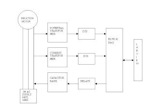
Improving Power factor of an Induction motor drive using Labview

Improving Power factor of an Induction motor drive using Labview
Virtual instrumentation deals with acquiring, analysing and presenting data. It offers more flexibility than traditional instruments and proves to be ideal for signal processing and simulation. It is popularly used due to its graphical nature, versatility and easy programmability. The program can be changed at any point of time according to the needs of the user.
A project which deals with the power factor determination and correction of a lagging power factor load such as Induction motor drive is discussed here. A three phase Induction motor is used as the load which normally draws lagging current. The current and voltage waveforms are obtained through current and potential transformers from the line side respectively. The sinusoidal waveform is given to zero crossing detector to produce square waveform which is then given to X-Or gate. This produces a signal which is nothing but the difference of the phase angle between current and voltage waveforms. The signal is then fed to the PC using DAQ (Data Acquisition) card. After acquiring the signal, the power factor is calculated using Lab view software and depending on whether leading or lagging, a pulse is generated. This pulse is used through DAQ card to correct the capacitance value on the line in order to improve the power factor

Friday, July 10, 2009

Speed Control of Switched Relectance Motor with DSP controller

Speed Control of Switched Relectance Motor with DSP controller
In construction, the switched reluctance motor (SRM) is the simplest of all electrical machines and most rugged one. The highly non linear relationship of the SRM are due to its single excited (exciting the stator only) double- salient and highly nonlinear machine characteristics. SRM drives can be controlled only by synchronising the energisation of the motor phases with the rotor position. Hence, the control of SRM is a tough one to deal with.

The increase in need for variable speed drives in industry and consumer application has seen renewed interest in the SRM. SRM is widely used in high performance servo applications such as aerospace, industrial and robotics.

SRM cannot be run directly from the supply. It can be run only when the motor is integrated with power converter, controller and rotor position sensor. So its essential to design high performance digital controller for SRM to get the optimum performance in the presence of the parameters variations and load disturbances.

The best solutions to control a switched reluctance motor is the usage of TMS320C24x. This new DSP family enables cost-effective design of intelligent controllers for switched reluctance motors. A novel speed control
algorithm is used to allow the Switched Reluctance motor drive to reach high efficiency, smooth operation, very good dynamic behavior, very high speed and low accoustical noise. All these solutions use only TMS320C24x resources, thus providing a single chip cost efficient control structure.

Wednesday, July 8, 2009

World's Cleanest Electric Bike

World's Cleanest Electric Bike
Electric vehicles do not normally emits carbon. The Zero Motorcycles from Calif., have unveiled a Zero X electric bike with zero emissions. This bike is the lightest, quietest and least polluting off-road bike. The features of this bike
* with 64Kg - which is half of the weight of a gas powered motorcyles
* with 20HP electric motor - speed is 0-48 Km/Hr.
* with lithium -ion battery pack runs 60 Km on a 2 Hr. battery charge
* It can be rided on mountain and can handle higher jumps.
Howerver the bike cost is too high say $7450

Tuesday, July 7, 2009

Brain wave controller for disabilities

Brain wave controller for disabilities
This revolutionised technology is used to control a wheel chair driven by a disabled person by using his mind control. The thoughts steer the vehicle wherever he wish to go. Brain nerve cells create electric signals in the order of Micro level. These signals can be picked by using EEG ((Electro-encephalogram) detector.

This detector is fitted to the wheelchair with a display unit. By thinking about the direction of the movement, the electrodes of the EEG unit detect the brain signals and then respond by turning left or right and moving in the desired direction. Toyota, and the Japanese research foundation have created such a wonderful device for the welfare of lives of paraplegics.
Once these devices hit the market, there will be a lot of relief to the disabled. Thanks to the researcher who have done this wonderful job.

Monday, July 6, 2009

Distributed intellegence in day to day electrical and electronics appliances

Distributed intellegence in day to day electrical and electronics appliances
Distributed intellegence which is normally hidden inside the products that we use in day to day appliances is revolutinising this world and has been doing wonders. This embedded information processing revolution has created a new path in controling electrical and electronics appliances. For example, in a washing machine the amount water required for washing is adjusted accroding to the dirty and load size. For this purpose, a Microcontroller is used to do this job. A single appliance may be equiped with a number of microcontrollers to accurately control the appliances.
This distributed intellegence can be categorized as
1. In consumer segment which includes home appliances and entertainment equipment
2. In Automative field where a moder car is embedded with more than 50 micro controllers
3. Office automation, which includes PCs, Keyboard, copier machines, printers and so on
4. Telecommuncation field includes cellular phones, pagers and so on
5. The major usage of this intellegence is industry and so on

This intellegence is a second revolution next to microprocessor based, what would be the next technology? is there any such intellegence, give your valuable suggestions.

Thursday, July 2, 2009

Features of PIC 16C7x Microcontroller

Features of PIC 16C7x Microcontroller
Pic Microcontrollers are commonly used in Engineering Projects. It can be used as a portable controller in any applications. I would like to share its immense features compared with conventional microcontrollers.
1. High-performance RISC CPU
2. Only 35 single word instructions and All are single cycle instructions except for program branches which are two cycle
3. Operating speed: DC - 20 MHz clock input, DC - 200 ns instruction cycle
4. Up to 8K x 14 words of Program Memory,up to 368 x 8 bytes of Data Memory (RAM)
5. Interrupt capability
6. Eight level deep hardware stack
7. Direct, indirect, and relative addressing modes
8. Power-on Reset (POR), Power-up Timer (PWRT) and Oscillator Start-up Timer (OST)
9. Watchdog Timer (WDT) with its own on-chip RC
10. oscillator for reliable operation
11. Programmable code-protection
12. Power saving SLEEP mode
13. Selectable oscillator options
14. Low-power, high-speed CMOS EPROM technology
15. Fully static design
16. Wide operating voltage range: 2.5V to 6.0V
17. High Sink/Source Current 25/25 mA
18. Commercial, Industrial and Extended temperature ranges
19. Low-power consumption:

Peripheral Features:
• Timer0: 8-bit timer/counter with 8-bit prescaler
• Timer1: 16-bit timer/counter with prescaler,can be incremented during sleep via external crystal/clock
• Timer2: 8-bit timer/counter with 8-bit period register, prescaler and postscaler
• Capture, Compare, PWM module(s)
• Capture is 16-bit, max. resolution is 12.5 ns, Compare is 16-bit, max. resolution is 200 ns, PWM max. resolution is 10-bit
• 8-bit multichannel analog-to-digital converter
• Synchronous Serial Port (SSP) with SPI
• Universal Synchronous Asynchronous Receiver Transmitter (USART/SCI)
• Parallel Slave Port (PSP) 8-bits wide, with external RD, WR and CS controls
• Brown-out detection circuitry for Brown-out Reset (BOR)

Wednesday, July 1, 2009

Internet-based SCADA systems

Internet-based SCADA systems

The Internet has now been dedicating a new and highly-efficient medium for sharing information all over the world. The development of web technologies allows information to be displayed numerically and graphically on any conventional Internet browser. Via Internet browsers (or web-browsers), end users can access, monitor the real-time data and even control the field devices and equipments.
Supervisory Control and Data Acquisition (SCADA) systems are now becoming more and more popular in industrial processes and the demands in functionality and high performance have been increasing rapidly. Furthermore, the fast development of microprocessor manufacturing and Internet technology makes it more efficient and cost-saving to design such systems with the embedded network protocol modules.
Overall block diagram
A best solution on implementing Internet-based SCADA systems is with the presence of embedded TCP/IP Protocol stacks. The solution provides the following features:
• Automatically collect the latest system’s data and real-time data are displayed on web-browser interfaces.
• Users can manage and issue command controls on system’s devices from any internet-connected place.
• Security issue is carefully considered with: server protection by router; user authentication & IP approval on server application software and MD5 algorithm for data encoding. This helps reduce the threat of the public nature of the Internet.
• New sites/devices can be added/deleted/tracked.
• System operation can be tracked for each user by the event log tool.
These type of decentralised control can be more efficient and fast compared with conventional methods.