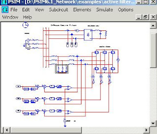
PSIM software
I have already discussed about various simulation software in previous blogs. In this connection, i would like to bring more about PSIM software which will be very useful for doing projects at UG and PG level. On request of some of our net friends, i would like give a details of PSIM software with an example.
PSIM is a simulation package specifically designed for power electronics and motor control. With fast simulation and friendly user interface, PSIM provides a powerful simulation environment for power electronics, analog and digital control, and motor drive system studies. PSIM is having three add-on Modules: Motor Drive Module, Digital Control Module, and SimCoupler Module. The Motor Drive Module has built-in machine models and mechanical load models for drive system studies. The Digital Control Module provides discrete elements such as zero-order hold, z-domain transfer function blocks, quantization blocks, digital filters, for digital control analysis. The SimCoupler Module provides interface between PSIM and Matlab/Simulink2 for cosimulation. The PSIM simulation package consists of three programs: circuit schematic program PSIM, PSIM simulator, and waveform processing program SIMVIEW1.

Typical uses of the software include.
• Math and computation
• Algorithm development
• Data acquisition
• Modeling, Simulation and prototyping.
• Data Analysis, Exploration and Visualization
• Scientific and Engineering graphics
• Application development, including graphical user interface building.
A circuit is represented in PSIM in four blocks: power circuit, control circuit, sensors, and switch controllers.
The power circuit consists of switching devices, RLC branches, transformers, and coupled inductors. The control circuit is represented in block diagram. Components in s domain and z domain, logic components (such as logic gates and flip flops), and nonlinear components (such as multipliers and dividers) are used in the control circuit. Sensors measure power circuit voltages and currents and pass the values to the control circuit. Gating signals are then generated from the control circuit and sent back to the power circuit through switch controllers to control switches.
Example:
To simulate the sample one-quadrant chopper circuit “chop.sch”:
• Start PSIM. Choose Open from the File menu to load the file “chop.sch”.
• From the Simulate menu, choose Run PSIM to start the simulation. The
simulation results will be saved to File “chop.txt”. Any warning messages
occurred in the simulation will be saved to File “message.doc”.
• If the option Auto-run SIMVIEW is not selected in the Options menu, from the Simulate menu, choose Run SIMVIEW to start SIMVIEW. If the option Auto-run SIMVIEW is selected, SIMVIEW will be launched automatically. In SIMVIEW, select curves for display.
PSIM is a simulation package specifically designed for power electronics and motor control. With fast simulation and friendly user interface, PSIM provides a powerful simulation environment for power electronics, analog and digital control, and motor drive system studies. PSIM is having three add-on Modules: Motor Drive Module, Digital Control Module, and SimCoupler Module. The Motor Drive Module has built-in machine models and mechanical load models for drive system studies. The Digital Control Module provides discrete elements such as zero-order hold, z-domain transfer function blocks, quantization blocks, digital filters, for digital control analysis. The SimCoupler Module provides interface between PSIM and Matlab/Simulink2 for cosimulation. The PSIM simulation package consists of three programs: circuit schematic program PSIM, PSIM simulator, and waveform processing program SIMVIEW1.

Typical uses of the software include.
• Math and computation
• Algorithm development
• Data acquisition
• Modeling, Simulation and prototyping.
• Data Analysis, Exploration and Visualization
• Scientific and Engineering graphics
• Application development, including graphical user interface building.
A circuit is represented in PSIM in four blocks: power circuit, control circuit, sensors, and switch controllers.
The power circuit consists of switching devices, RLC branches, transformers, and coupled inductors. The control circuit is represented in block diagram. Components in s domain and z domain, logic components (such as logic gates and flip flops), and nonlinear components (such as multipliers and dividers) are used in the control circuit. Sensors measure power circuit voltages and currents and pass the values to the control circuit. Gating signals are then generated from the control circuit and sent back to the power circuit through switch controllers to control switches.
Example:
To simulate the sample one-quadrant chopper circuit “chop.sch”:
• Start PSIM. Choose Open from the File menu to load the file “chop.sch”.
• From the Simulate menu, choose Run PSIM to start the simulation. The
simulation results will be saved to File “chop.txt”. Any warning messages
occurred in the simulation will be saved to File “message.doc”.
• If the option Auto-run SIMVIEW is not selected in the Options menu, from the Simulate menu, choose Run SIMVIEW to start SIMVIEW. If the option Auto-run SIMVIEW is selected, SIMVIEW will be launched automatically. In SIMVIEW, select curves for display.

2 comments:
i am mohamad hassim....i would like to ask about how to design an active filter an passive filter in psim...i mean which element can i choose?...this is my email...mohamad_hassim@yahoo.com...i hope you can help me...thank you....=)
How much this software costs?
Post a Comment